project01:Prototype
(→Structural Prototype) |
(→Structural Prototype) |
||
| Line 74: | Line 74: | ||
[[File:P01 Prototype 3.jpg| 850px]] | [[File:P01 Prototype 3.jpg| 850px]] | ||
| − | + | [[File:P01 Digital Prototype .jpg| 850px]] | |
<!-- start top block --><div style="width: 840px; height: 120px; border: 1px solid #C0C0C0; padding: 5px; margin: 0;"> | <!-- start top block --><div style="width: 840px; height: 120px; border: 1px solid #C0C0C0; padding: 5px; margin: 0;"> | ||
<!-- start front image column--> <div style="float:left; width: 830px; padding:5px; Padding: 5px;margin: 0;"> | <!-- start front image column--> <div style="float:left; width: 830px; padding:5px; Padding: 5px;margin: 0;"> | ||
| Line 82: | Line 82: | ||
Prototype 3 (1:20) was the combination of the 1st and 2nd prototype; allowing flexible formations. it was successful in providing sliding and rotation movements, but failed to provide the elevation rotation; this is due to the individual round connectors being too small to control and often came out of the railing. | Prototype 3 (1:20) was the combination of the 1st and 2nd prototype; allowing flexible formations. it was successful in providing sliding and rotation movements, but failed to provide the elevation rotation; this is due to the individual round connectors being too small to control and often came out of the railing. | ||
| + | '''Digital Prototype v3.1''' | ||
| + | The Digital Prototype allows us to confirm that despite the model prototype is | ||
| + | unable to adjust in a 3D manner, that the structural system design can be adjusted both 2D and 3D co-ordinates. | ||
<!-- end front image column--></div> | <!-- end front image column--></div> | ||
<!-- end top block --></div> | <!-- end top block --></div> | ||
| − | |||
| − | |||
=Interior Prototype= | =Interior Prototype= | ||
Revision as of 16:31, 9 May 2012
Site Map: Home || Wen Tao Bi
Contents |
Recap of Phase I
New Urban Intervention
Dancing with Robots
The question left from Phase 1: The Challenge is how can robotic architecture provide a new intervention for architectural systems? how can robotics be apart of architecture rather than be an additional machine used as a manipulator? what can robotics provide where other technological system cannot?
The aim of the Phase 2: The Prototype is to explore these questions, and provide solutions or conclusions upon the robotic arm's potential in architecture.
Just some food for thought: what if architecture can be changed in real time with an robotic arm; in a way " Dancing with Robots "
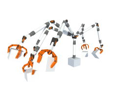
The Robotic Arm
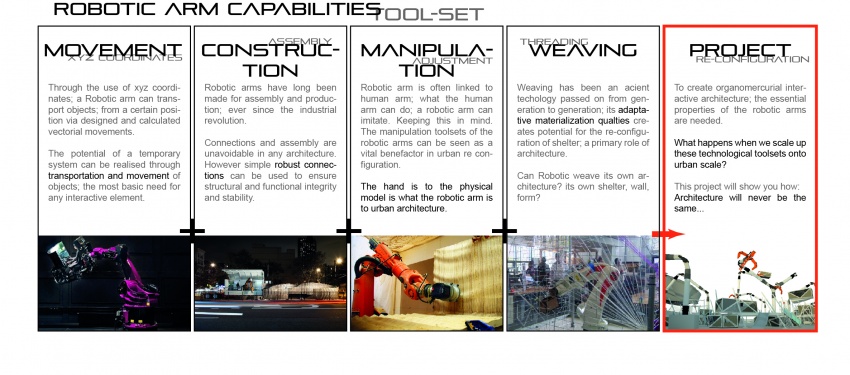
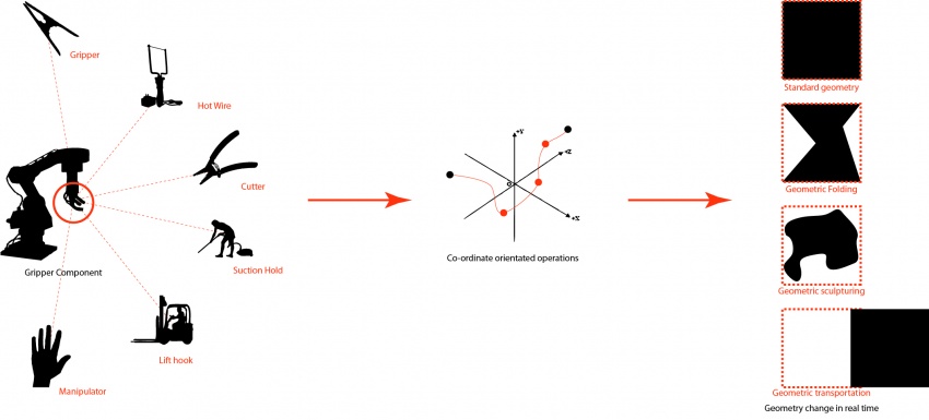
The main feature of the Robotic arm is it's multi-axial rotation and its gripper. The only changeable, flexible component however is the gripper. therefore the different designs of the gripper allow different manipulation of the object. sample grippers include: Hot wire Grippers, Suction Grippers, Clamp Grippers, Multi-Finger Grippers, Cutter Grippers etc...
each of these grippers provide a special manipulation tool which can be used to change an object. whether it is transporting, cutting, sculpturing, folding, pushing or pulling. how can these elements be used to change architectural qualities? what would be the outcome of this new intervention?
Robotic Prototype
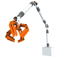
The Robotic arm is created to allow maximum flexibility. standard industrial robotic arms only have 3 point axial rotation; this has very limiting range of co-ordinates as the body itself is not long enough to reach the location around the base of the robotic arm.
To keep the concept simple, we have selected the combination of multi-finger + suction gripper as the manipulation tool for Urban Arm v1.0 by using these combinations, we are able to move objects or components in different directions (pushing and pulling.) hence the new manipulation method is created. a new structure needs to be formed.
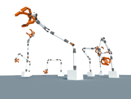
The robotic arm is 30m in length; providing a movable span of 25m. this allows great variation in co-ordination. along the site multiple robotic arms can be in place to coordinate stigmeric-scape configurations.
Structural Prototype
Prototype v1.0
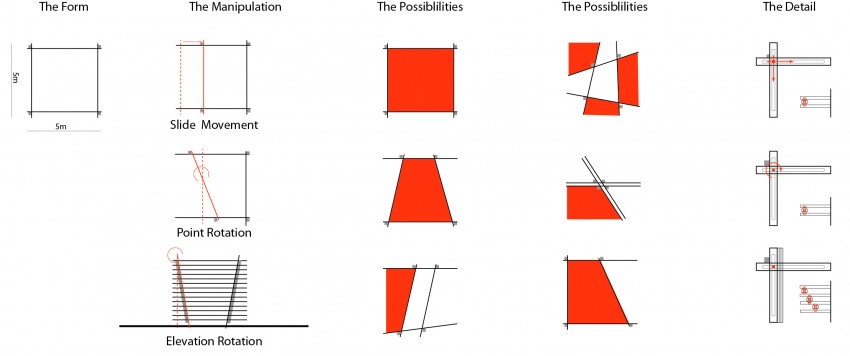
Prototype v1.0 (1:20):Through the adaptation of the structure, a component where it can be flexible in both its scale and shape. the wall can be slided across or rotated in both vertical and horizontal planes. this creates a large number of variation to cater for the different functions described in Phase 1. (functions include: toilets, energy sources, cafes, shops, offices, gallery, waiting areas, plaza, outdoor recreation areas etc...)
Prototype v 2.0
Prototype 2 (1:20) was an exploration of the predefined conditions; how can walls be slided and rotated to form new forms, plans and configurations. the connectors are small rounded components used for sliding and rotating the walls, they are independent and thus allows the wall to move in a 3 dimensional formation.
Prototype v 3.0
Prototype 3 (1:20) was the combination of the 1st and 2nd prototype; allowing flexible formations. it was successful in providing sliding and rotation movements, but failed to provide the elevation rotation; this is due to the individual round connectors being too small to control and often came out of the railing.
Digital Prototype v3.1 The Digital Prototype allows us to confirm that despite the model prototype is unable to adjust in a 3D manner, that the structural system design can be adjusted both 2D and 3D co-ordinates.
Interior Prototype

